So a little detour. I de-soldered the so-called MaskROM from a cartridge. Read on to find out what game I destroyed! It was very easy and I'm beginning to think that this should have been how I extracted data from my first cartridge. Oh well sometimes a harder problem is more interesting to solve. If you always get the easiest problem, you never get to make something really hard (since you'll always be good enough not to be challenged).
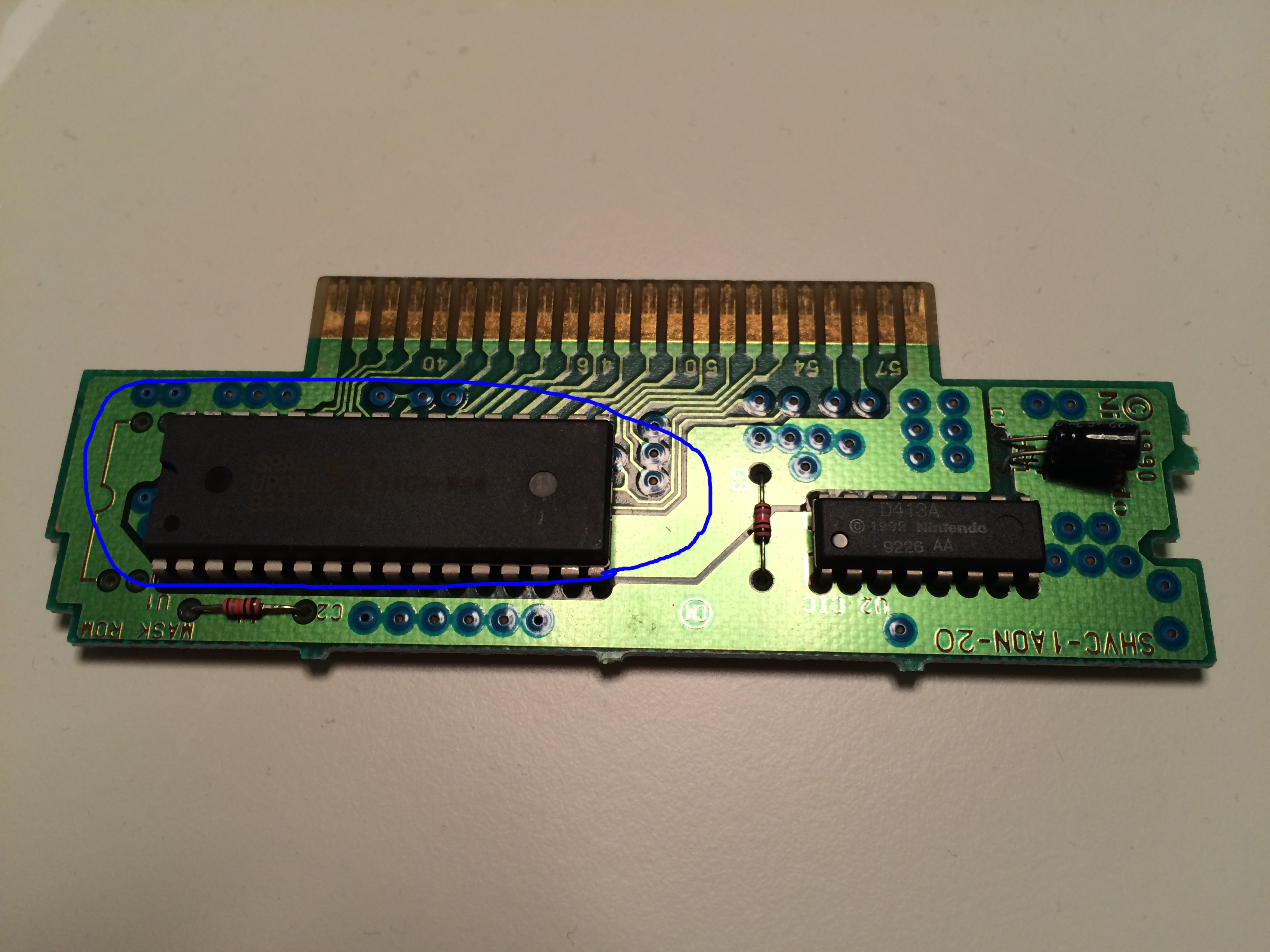
Let's start the show and tell! MaskROM inside the cartridge:
... and outside:
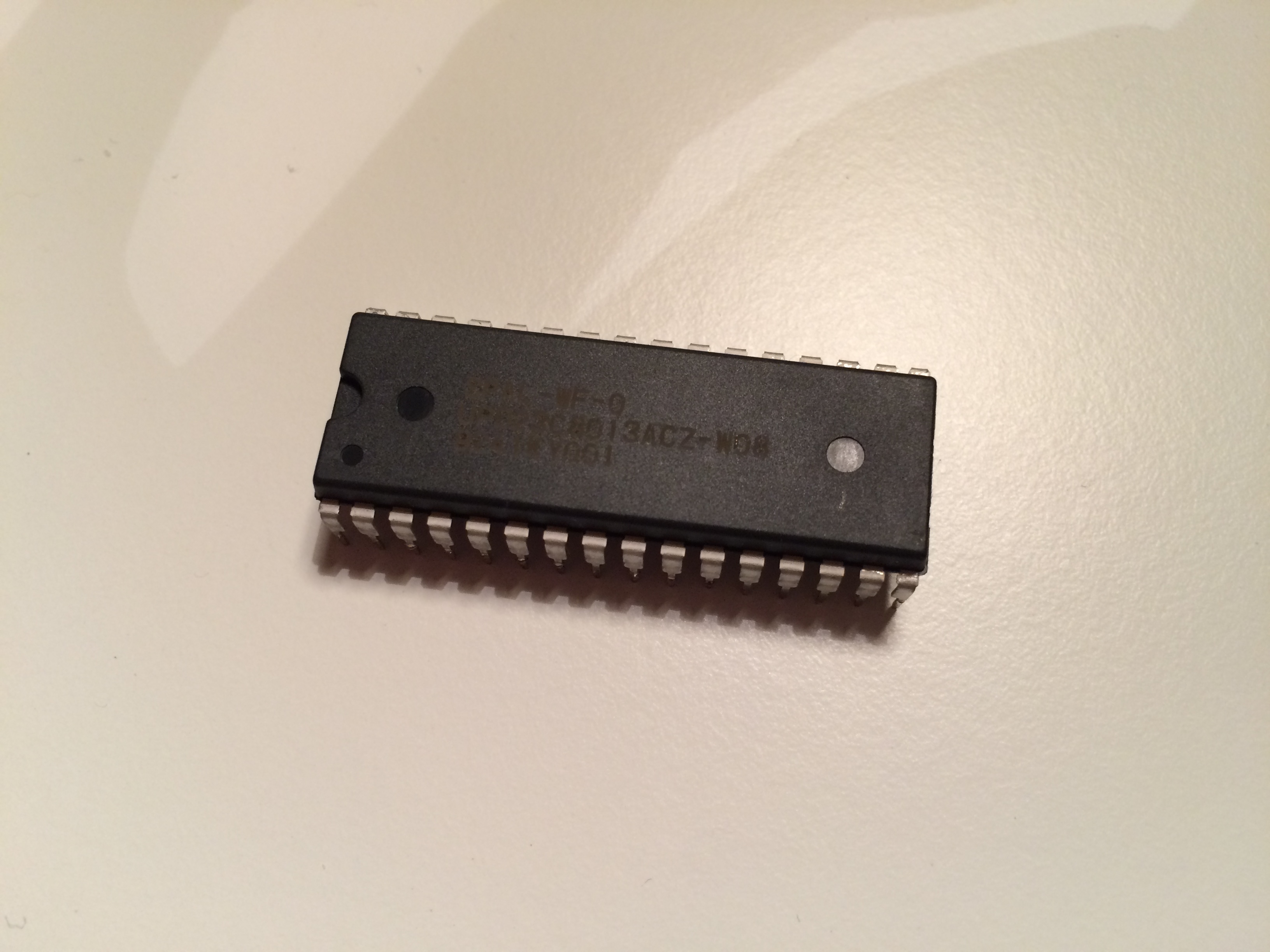
So what is the MaskROM? Well wikipedia tells me that a MaskROM is a very cost-efficient way to store read-only memory. The name is related to the manufacturing procedure. This particular MaskROM has 32 legs (pins) and contains 1MB.
Let me insert a figure from the snes pinout page:
32PIN MaskROM 36PIN MaskROM
===================== =====================
A17 01 32 Vcc A20 01 36 Vcc
A18 02 31 /OE A21 02 35 A22
A15 03 30 A19 A17 03 34 Vcc
A12 04 29 A14 A18 04 33 /OE
A7 05 28 A13 A15 05 32 A19
A6 06 27 A18 A12 06 31 A14
A5 07 26 A19 A7 07 30 A13
A4 08 25 A11 A6 08 29 A8
A3 09 24 A16 A5 09 28 A9
A2 10 23 A10 A4 10 27 A11
A1 11 22 /CS A3 11 26 A16
A0 12 21 D7 A2 12 25 A10
D0 13 20 D6 A1 13 24 /CS
D1 14 19 D5 A0 14 23 D7
D2 15 18 D4 D0 15 22 D6
Vss 16 17 D3 D1 16 21 D5
D2 17 20 D4
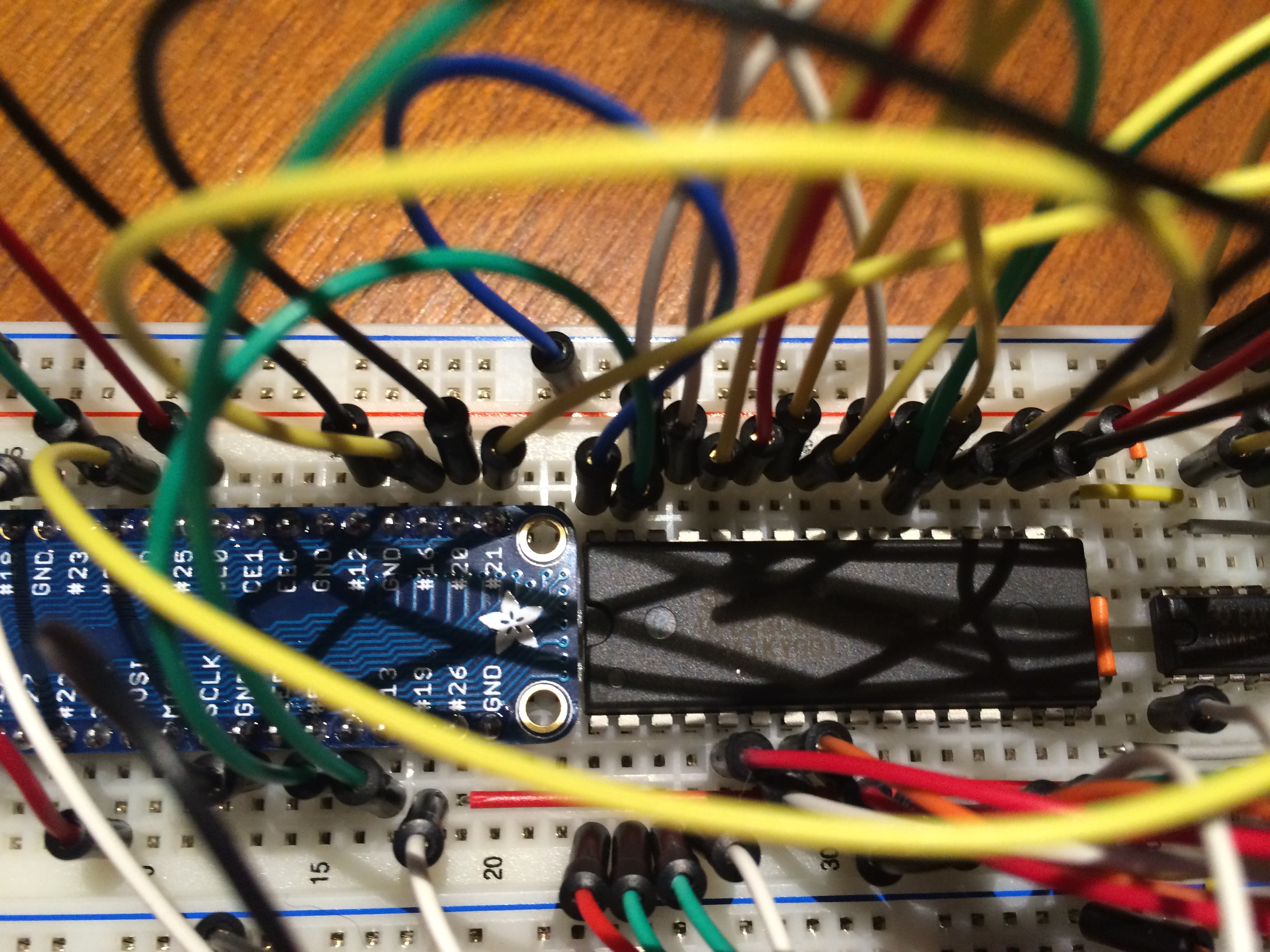
Vss 18 19 D3It shows the role of each pin. The D-pins are the 8-bit output data that is being read from the MaskROM. The address fed into the MaskROM does not have A15 going nowhere, all address pins are used. I inserted the MaskROM in my breadboard (yes, it is compatible!) and hooked it up to the RaspberryPI. My Raspberry does not have the 30 data-pins needed so I used my previous setup using counters to generate the adress. As usual I let it work at 3.3V instead of 5V to make sure the raspberry would survive. It looked something like this:
and from another angle
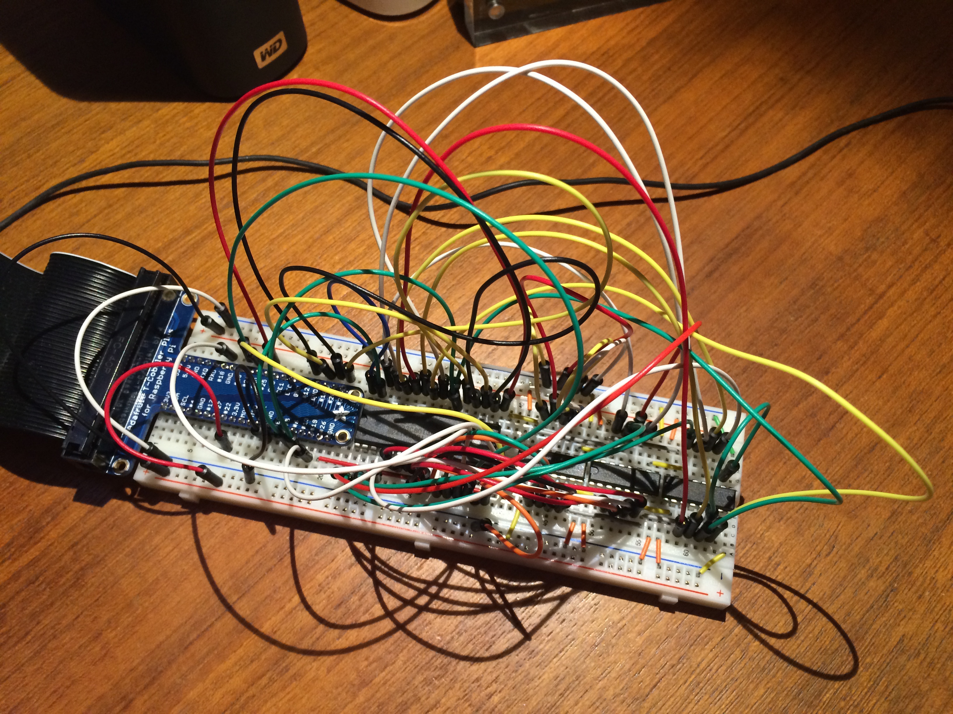
I've switched to dual 4-bit counters now which mean I can fit 24-bit adress generation using only 8*3=24 rows of the breadboard. However only 20-bits were needed today so 4 of the bits are fed straight to ground. In this cartridge each pin of the MaskROM is directly connected to a pin on the cartridge. For more advanced cartridges that supports save games (SRAM) or more advanced memory layouts that might not be true.
After much trial and error, as well as tearing it all apart and reverting to LED-debugging on each connection, it worked. The python program I ran was quite simple. It can be found here. The variables at the top specified to what data input/output I tied to pins on the MaskROM.
What did I do with the empty cartridge you might wonder? Let this image be a teaser!
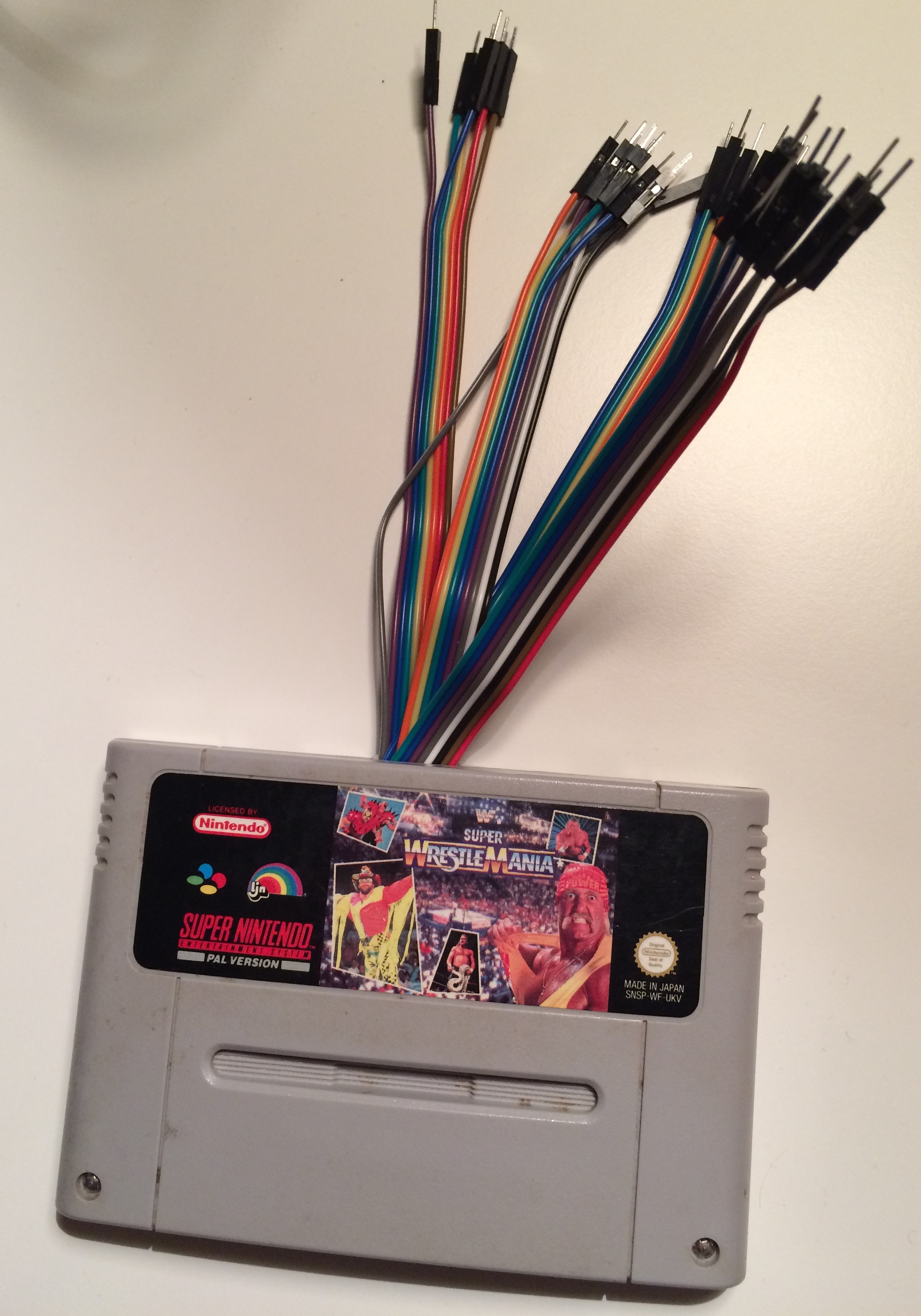
This image also says which cartridge I gutted. Hopefully it wasn't the last one!
That's all for this time!