Disclaimer: I still don't know what I'm doing so don't try to replicate what I have in my images!
So I finally hooked up my (now old!) raspberry to my breadboard. It was more involved than expected since once I sat down to start doing some experiments, it turned out that my raspberry breakout cable required soldering at 80 contact points. Luckily my last soldering side trip left me well prepared. I actually finished it quite fast. Or time went fast. Anyway it felt fast and that is the important part!
When I had the soldering iron up and running I also tried making a cable for my SNES project but I quickly realized that soldering wires requires some sort of mount so I'll get one before I'll continue that. Three hands would also help!
Anyway I started with the hello world of Raspberry-breadboard-interaction. One LED that I could control from python:
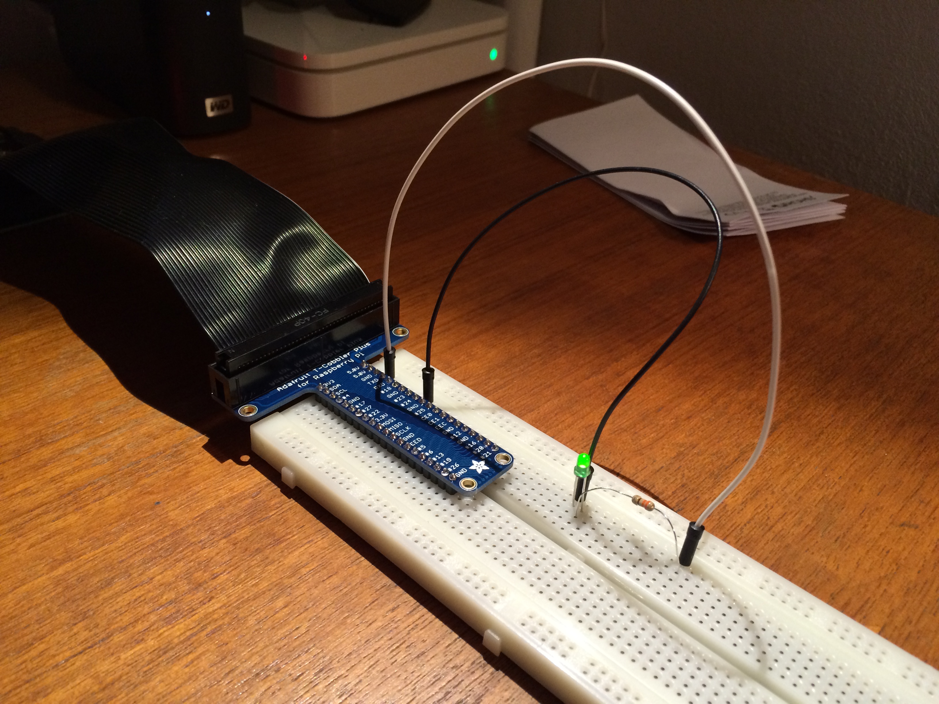
Quite satisfactory! I realize something about Ohm's law here too. I used to think that the resistor needed to limit the current would be different if I used one of the data pins or one of the +3.3/+5.0 pins. Turns out that the current drawn from the pin will be the same, independent of that pins ability to give out current. If resistance and voltage is known (say 330ohm and 3.3V as in my example) the current is given by Ohm's law directly, independent of the type of data pin used. While there is more “juice” in the +3.3V pin, it behaves as the data pins. It just doesn't break when you draw more!
Counters
To make things interesting I then experimented with a “counter”. I hook it up the ground and +3.3V on the raspberry. One data pin is connected to the CLOCK of the counter. Every time it goes from 0 to 1 the counter increases its' number. I hooked up the +3.3V to quite a lot of input pins of the counter that I just want to keep at 1. I'm not sure if I should add resistors to avoid short circuit... The counter shows the binary code of the current number on four of it's pins, and then once it overflows it shows a 1 on the carry pin. I hooked it up using a LED for each output pin (1,2,4,8,carry) to a visual debugging aid. I love those!
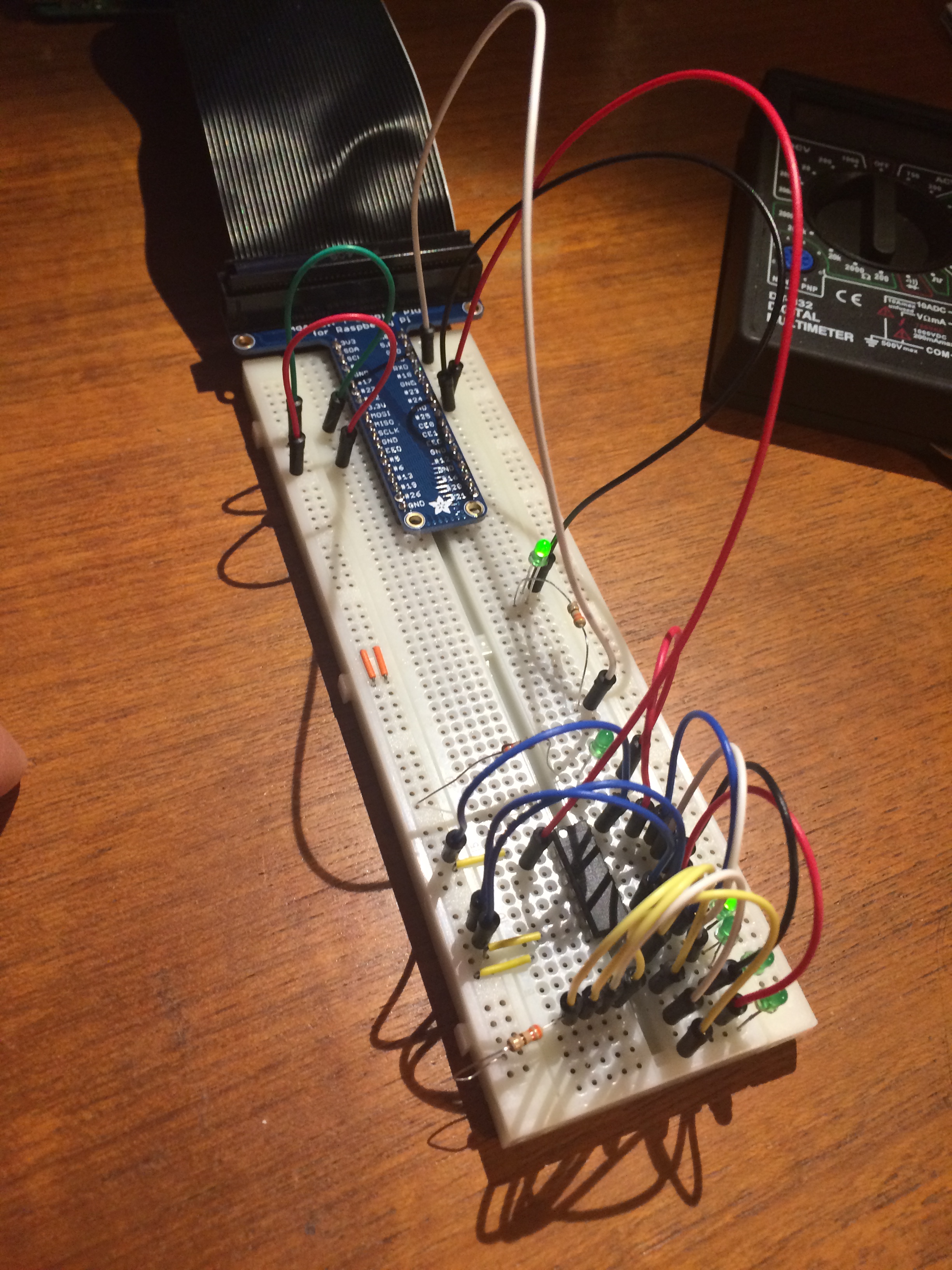
Quite messy!
Double Counters!
I then hooked up two of these in series. By connecting the CARRY from the first counter into the CLOCK of the second counter they work together.
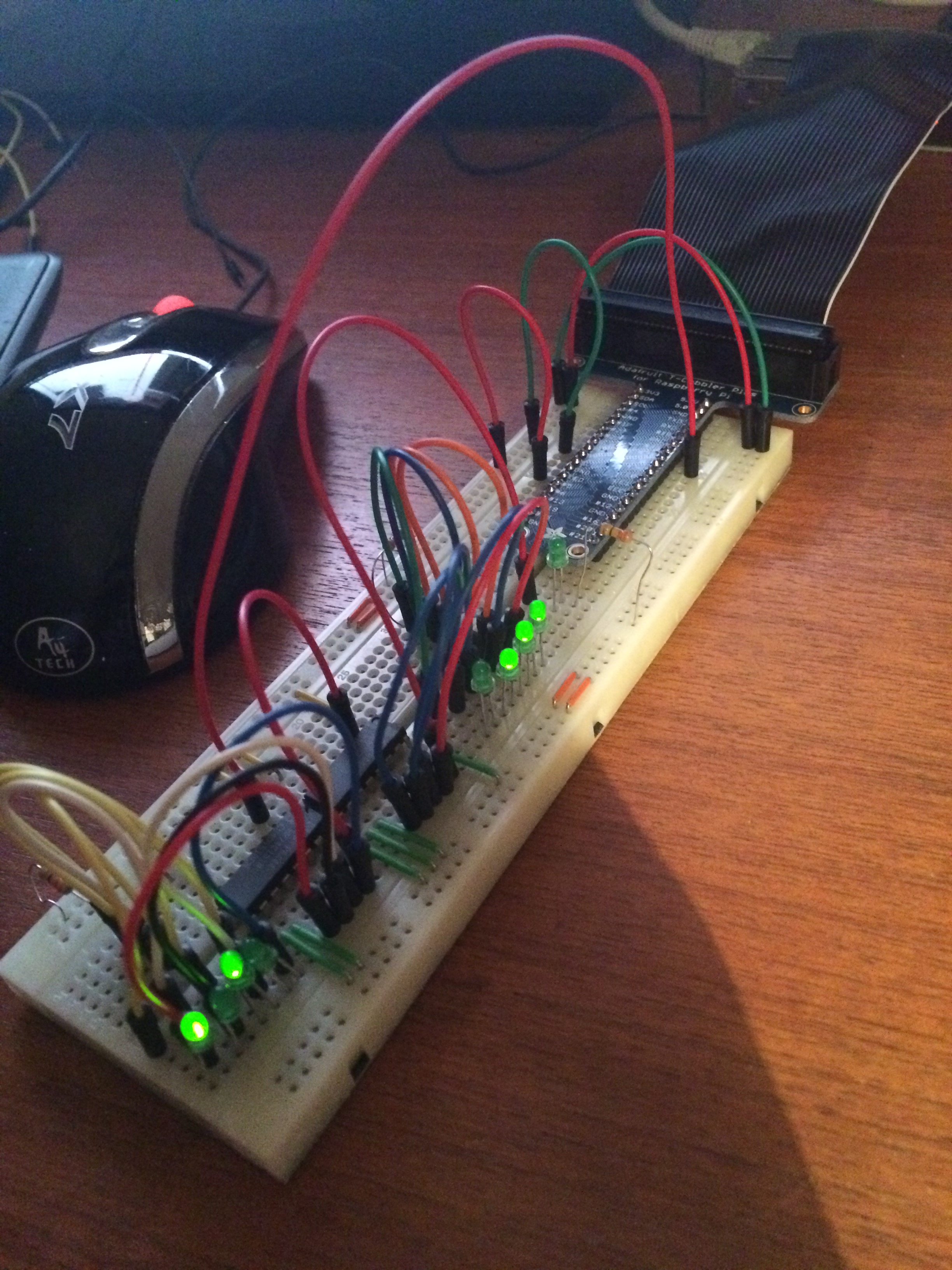
And from another angle:
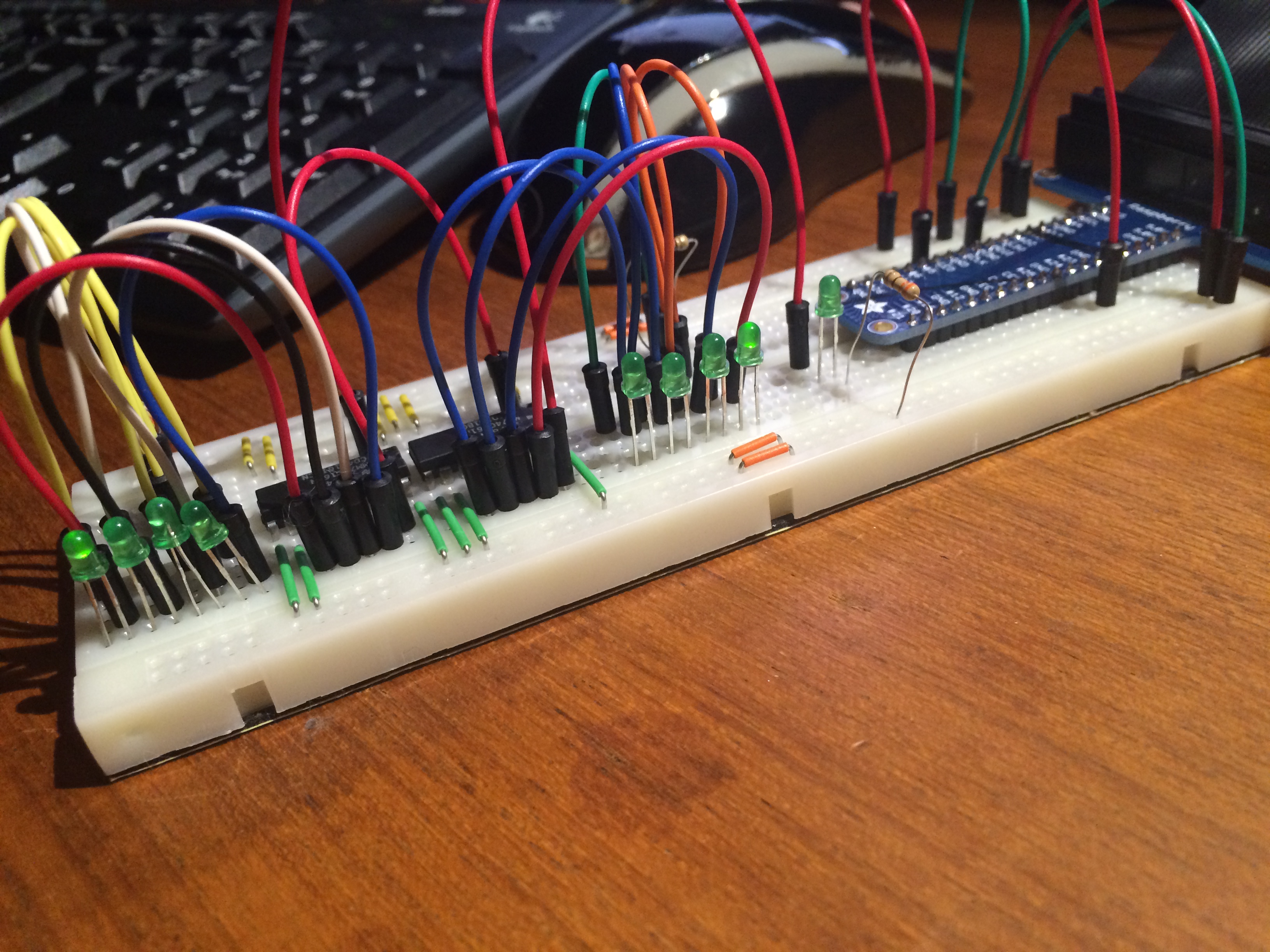
When I say work together I mean almost work together. I think that the second counter is activated one cycle too early. I have to figure out a way to delay the usage of the CARRY.
So why the counters? Well my current project is to extract ROM's from SNES cartridges. With 24 pins representing the adress to access I need a way to multiple the pins on the raspberry. But since I only intend to increase the binary number by one to get to the next byte I might as well use counters! Only one data pin required on the raspberry. With 24/4=6 counters I can generate 24-bits addresses.
Breadboard
So what do I think of the breadboard? Well it seems that some of my components are not really built for it. The resitors have too long legs, I really need to cut them. The counters are fragile and it is easy to damage them when taking them out of the breadboard. Perhaps there is a trick; I think they need to be lifted straight up. Working with soft cables is very nice for longer connections, but the hard cables makes it easier to look at the circuit and say what is going on.
When working with IC it would be nice to have a larger breadboard. If I plug in an IC like the counter it eats up 8 rows. If you look at how I had to with my LED's, I rather be able to do that sideways, straight out from the IC pin. Now I have to move them away vertically to get some room to work!
But in all it is has been really fun and I'm pleasantly surprised that I didn't kill my raspberry. Super happy that the counters worked on the first try!