My detour that I started in my previous post only had one logical next step.
When I de-soldered the MaskROM, I had to put something else on there. I put an angeled pin header in place with a rubber band like this:
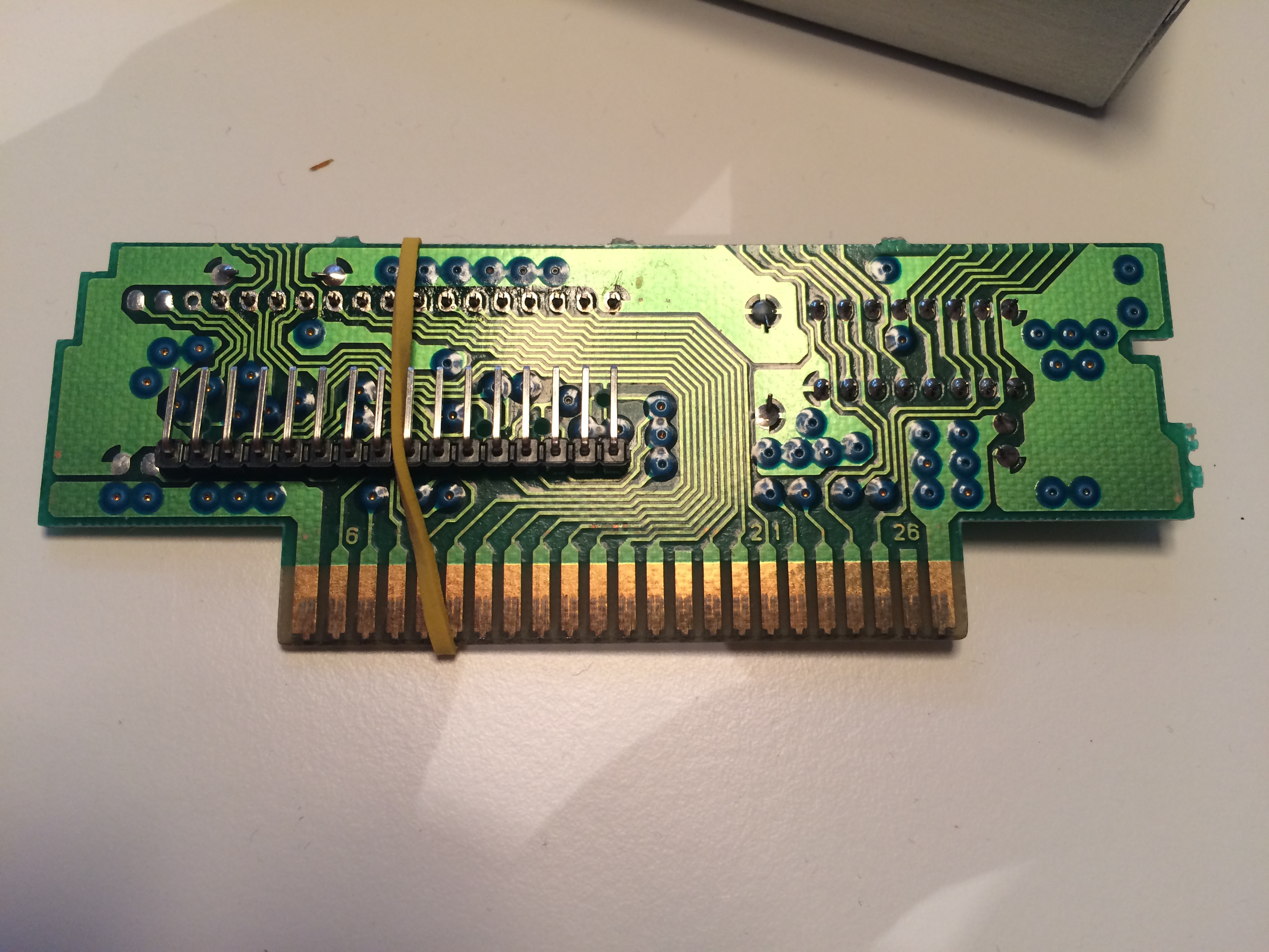
Very easy soldering. Once I had fixated the side points I removed the rubber band of course so it wouldn't melt. But wait the MaskROM had two sets of legs. If I could have put them both on the same side things would be easy, but the two pin headers would interesect. Annoying. I could put one on the other side, but the problem was that the holes in the PCB only allowed soldering from one side (no metal on the other). When the pin header was in place, the black plastic pieces would be ontop of my soldering points. In the end I raised the pin header slightly from the PCB. I then had access to the PCB and the pin header at the same time. I guess I melted some plastic, but it seemed to work. And it all fitted snuggly inside a closed cartridge!
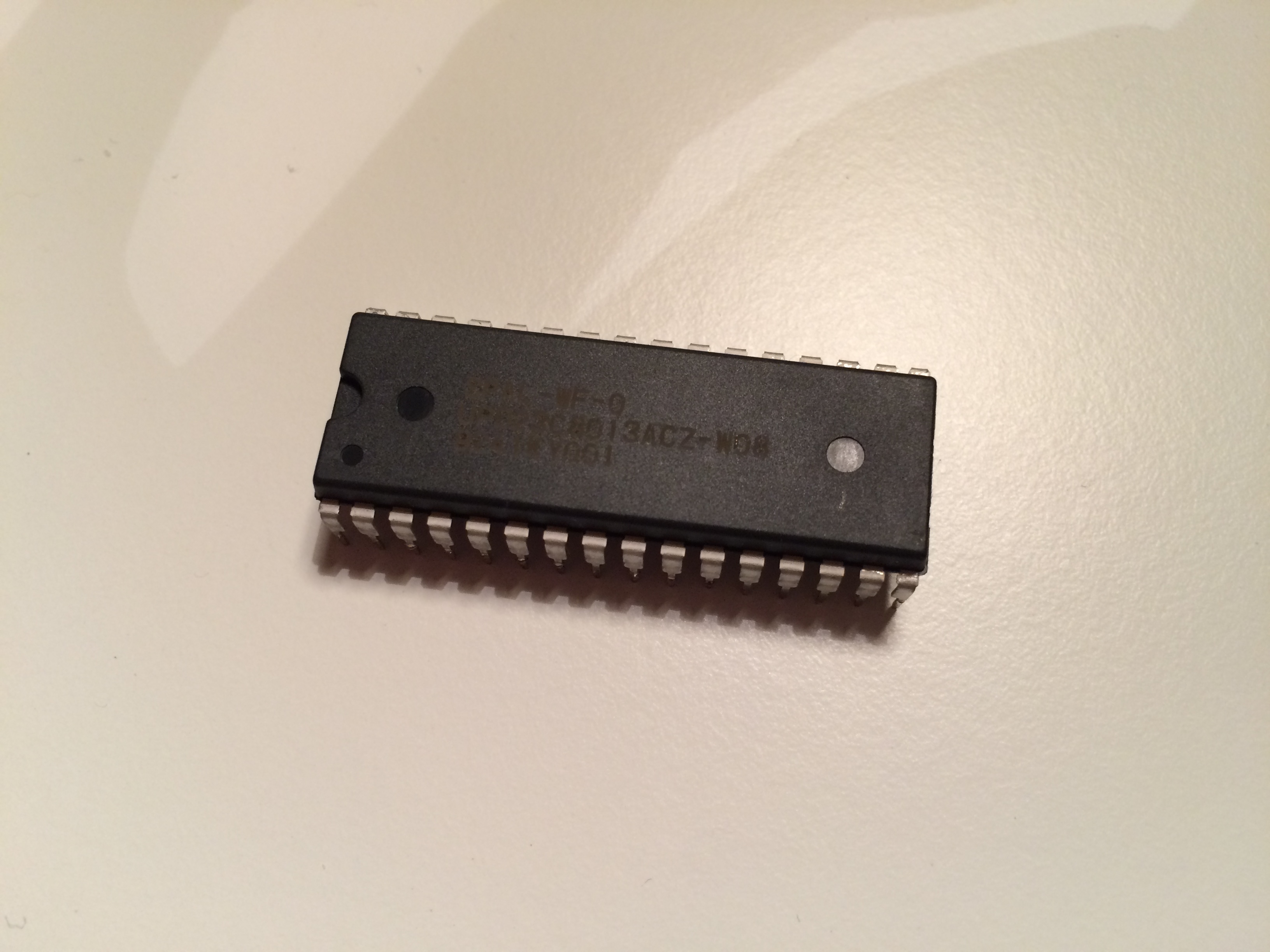
The extracted MaskROM looked like this:
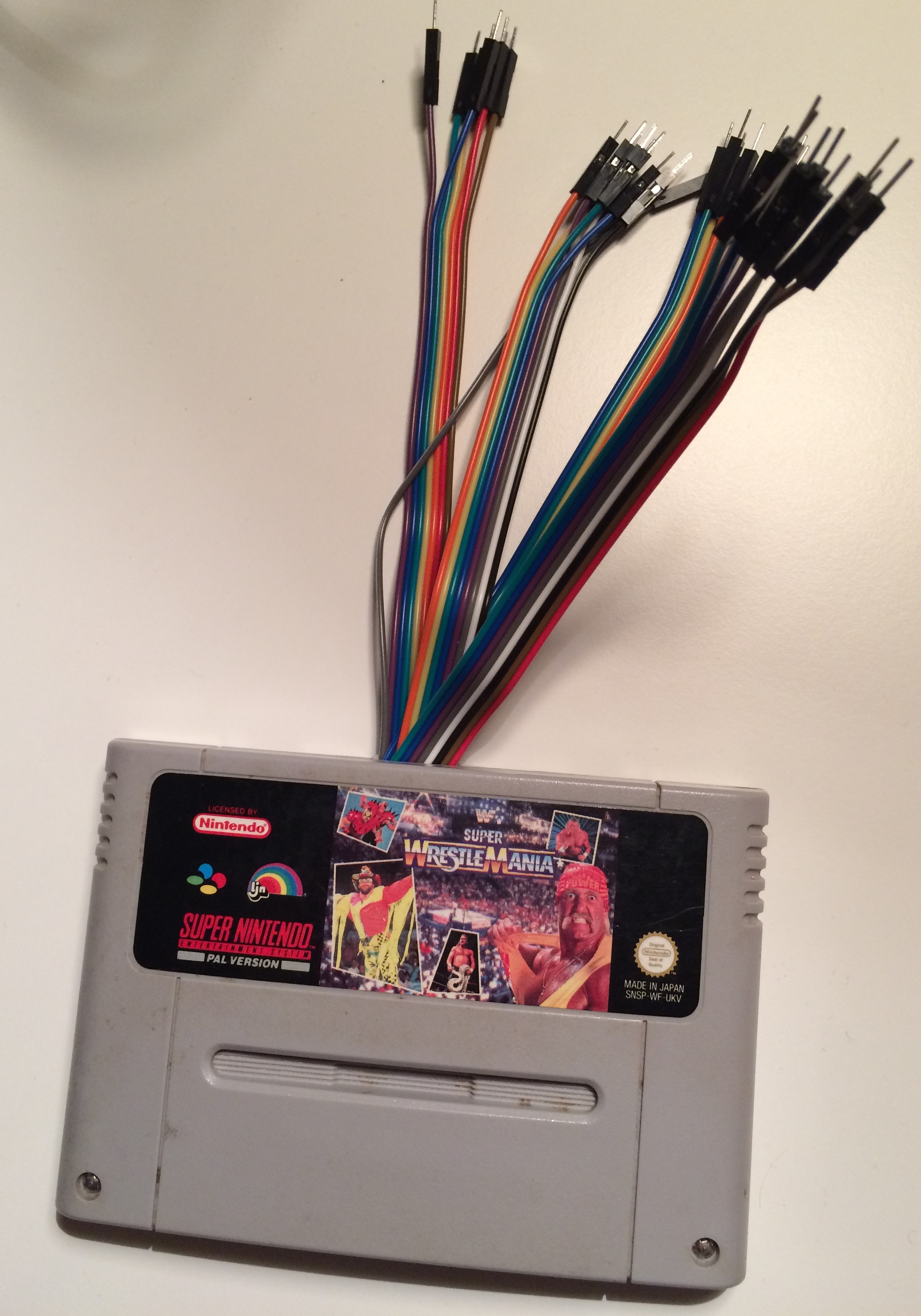
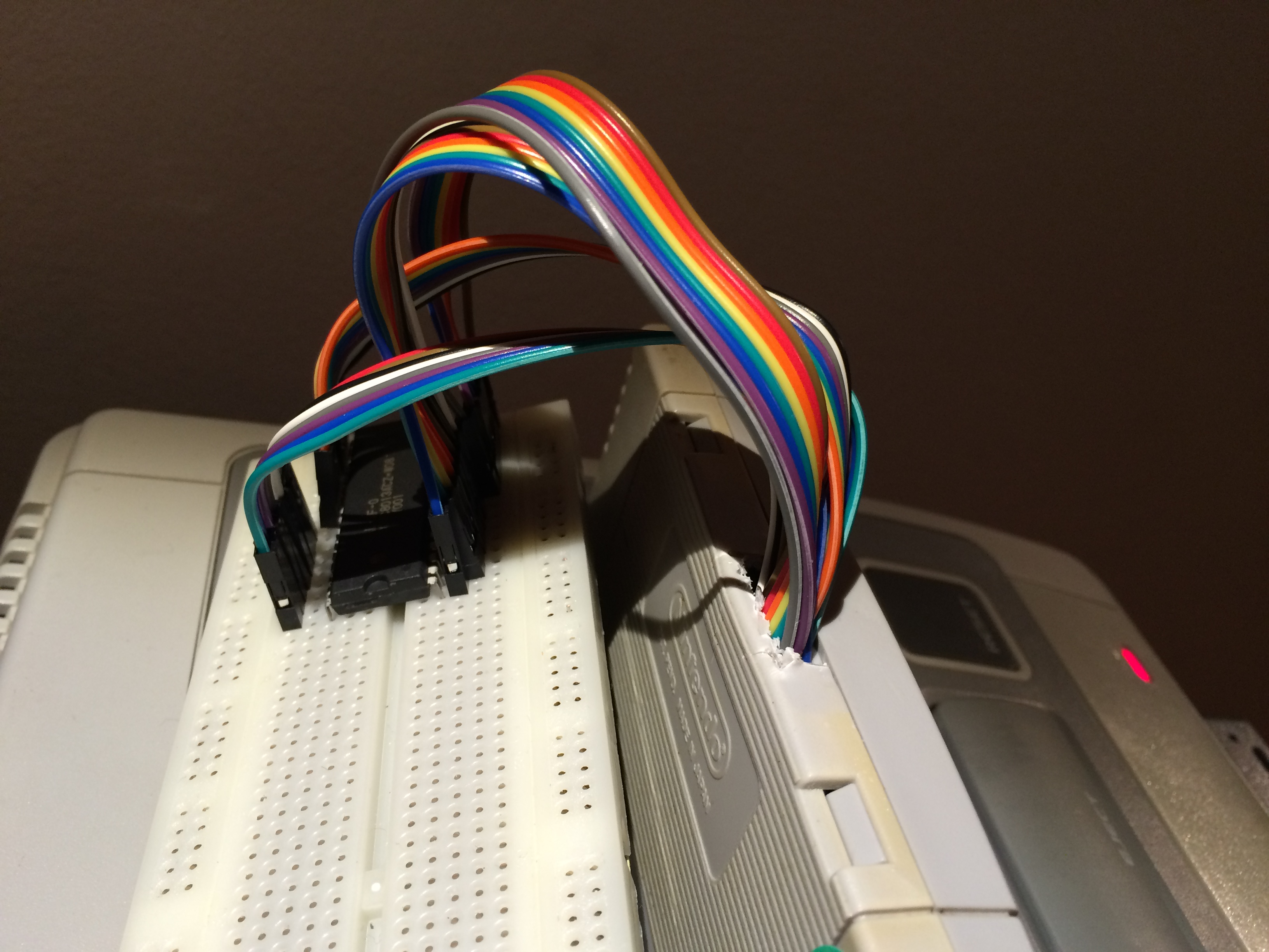
I had already put the MaskROM on a breadboard and there was only one logical thing to do. I had to connect them back together like they were ment to! This would be my first experiment with an actual running SNES. Since the cables were ment to be hooked into a MaskROM it was very easy to connect it correctly. It looked like this:
and the game looked like this
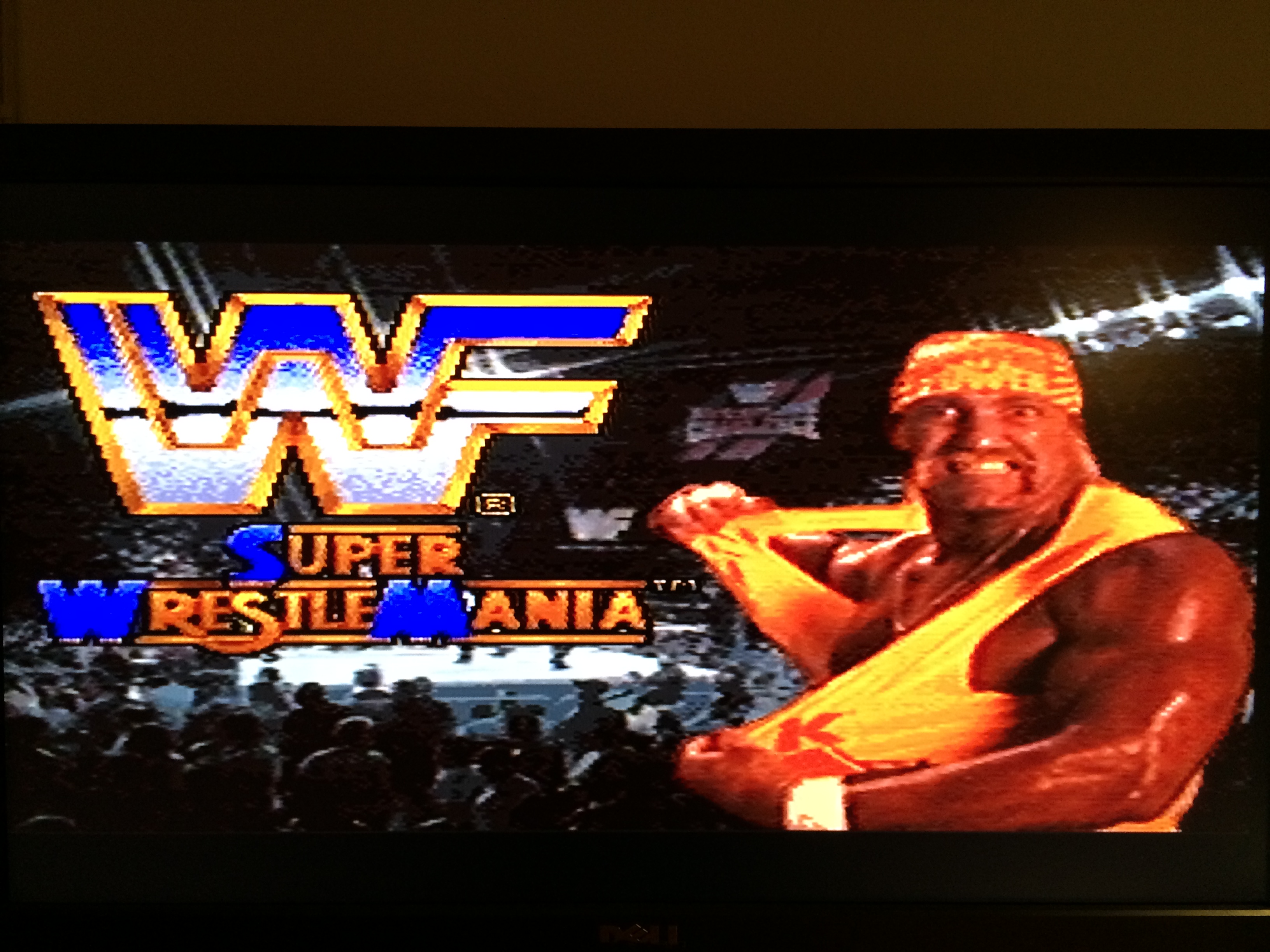
In retrospect I'm quite happy with the game I decided to gut. I did not enjoy it for even a second. Playing it on my 27" non-blurry-monitor didn't make it any prettier of course.
So what did I gain with this? Well now it will be very easy to monitor what happens on each leg of the MaskROM. How does it behave? What does the timing looks like? I could have done this without breakin out everything with cables, but it feels easier this way. Safer somehow. A friend will lend me his oscilloscope and from what I can tell it should be able to help me figure this out. Also I now have all the cables I need to simulate 1mb LoROM cartridges (I'm really making a 32-leg MaskROM simulator). On a breadboard. I'm still very worried that the Raspberry GPIO will not be fast enough - especially when I add multiplexers into the mix to be able to handle all the data pins - but the oscilloscope might help me answer some questions on what the SNES expects!